This article is Part III of a series called Track Your Adventures for Free where I outline how to use Ham Radio and your Smartphone as an affordable APRS tracking system. For reference, here are links to the first 2 parts:
In part II I closed on the mention of modifying the BaoFeng headset and a smartphone headset such that the speaker output of the BaoFeng radio is connected to the microphone input of the Smartphone, and also have the Smartphone speaker output connect to the BaoFeng radio’s microphone input. This is, for the most part, simple, but at Integrated Overland we like to build things that are technically sound and designed to remain functional. Yes, you could simply cut the wires off the ends of the cables and connect the Speaker + and – to the microphone + and -, but this will result in problems down the road that have the potential to damage either your radio or smartphone, or both. I am going to explain the technical details behind this, but I want to start off by ensuring you that doing it right is still a simple process and only requires adding 4 resistors. Don’t be discouraged by the tech talk, this is still very simple, and you can feel free to skip ahead if you just want to implement the solution. You can also skip the solution altogether and just pair the wires together, at the very end of the article I will discuss how to do this in a way that will minimize the risk, but given how simple the solution is, you may want to give it a shot.
So what’s the problem? The problem is that for both the radio and Smartphone, the speaker signals are designed to drive earphone speakers and produce audible noise. This means that the speaker outputs are higher power outputs. However, the microphone input for both and for most devices in general is designed to operate with low power signals that are generated by the microphone. This means that you are trying to put higher power signals from the speaker into a port that is designed for lower power signals. The speaker output levels for typical devices can range anywhere from 2V to 20V in amplitude (partially depending on the volume level). A microphone input level is typically on the lowest end of this spectrum at around 0.2V to up to around 2V. On an even more technical side note, the speaker and microphone ports have different impedance levels, but this is less important as we aren’t trying to achieve maximum signal transfer in either case.
So our basic problem is simple, we have a voltage level problem, we need to reduce the voltage, which is much easier than needing to amplify the voltage. We have to shift a 2V-20V signal into a 0.2V-2V signal. Incidentally, this is a 10 to 1 reduction, and because we all love technical details, we’ll mention this is a 20dB reduction.
The basic solution to a basic problem then becomes a basic voltage divider circuit (and the cessation of usage of the word basic). We need a 10:1 voltage divider, which can be achieved with 2 resistors. The resistors have to have a 10 to 1 difference to meet the criteria, so you can use a 1kΩ resistor, and a 100Ω resistor, or different combinations of 10 to 1 ratio values. However, I recommend that you use a 10kΩ resistor and a 1kΩ resistor. Why? Because this would put roughly a 10kΩ impedance on the speaker side (high side), and a 1kΩ impedance on the microphone side. This is more suitable for the application. Now, to properly cover the basics, below are 2 images of what this voltage divider circuit looks like.


These two circuits above are exactly the same. I simply wanted to illustrate that the way these are shown in the schematic is not relevant to its operation in case we have readers who are unfamiliar with schematics. What matters is the order, meaning that the input side has to enter into the higher value 10kΩ resistor, and then at the other side of the 10kΩ resistor, you tap your output, but this same point is connected to ground via the 1kΩ resistor. How you lay it out in application does not matter as long as the connections are made at the correct point.
So we have solved the problem of reducing our signal levels, now how do we apply the solution to our particular problem? The answer is as follows:
Since we need to lower the speaker output levels on both the radio and the smartphone to each other, we will need 2 voltage divider circuits and will have to use a total of 4 resistors. The schematic below shows what the final circuit will be.

Now that we have established what we need to build, lets discuss how its actually made. Schematics are useful to illustrate how we are going to make the connections, but now I’m going to show you some photos of what the actual pieces look like and how we’ll be cutting them up. To start, the image below shows what a Smartphone headset connector looks like.

In the above image, you can notice that there are 4 sections of metal contacts on the connector, separated by the white rings (can be different colors). Each section represents a different contact. For the Smartphone connector, the top most contact (1) is the Left Speaker +, the next (2) is the Right Speaker +, next (3) is Ground, which is a common ground, so it represents ground for the left and right speaker, as well as the microphone. Finally, contact (4) is the microphone +. Because there are so many different headsets or cable options for the Smartphone side, I won’t include a cut out which shows the wires and colors. You will have to cut the other end of your particular connector and identify the wires yourself. When you cut the cable, you can identify which wire corresponds to each connector by running what is called a “Continuity Test” using a multimeter. If you don’t own a multimeter I recommend the MASTECH AC/DC Auto/Manual Range Digital Multimeter, MS8268 if you want a low cost but long term hobby grade piece of equipment, or this very cheap DT830B LCD Digital Voltmeter Ammeter Ohm Multimeter
for a very functional but less durable and precise option that’s only a few dollars.
On the radio side, you will take the included headset and cut into it where the Push-to-Talk switch is located. Note, you can always buy a replacement headset here: Baofeng Earpiece Headset Mic for Baofeng Uv-5r 666s 777s 888s Two-way Radio
The image below shows the BaoFeng connector with its 6 contacts labeled.
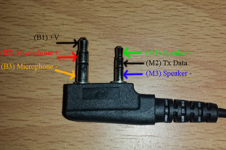
Notice that this connector has two 3 pin connectors, a big, which I have labeled B1 through B3, and a mini, which has labels M1 to M3. If you are using the headset that came with the radio, then chances are that the internals are the same so I will try and save you some time by showing you the photo below with the labeled connectors.
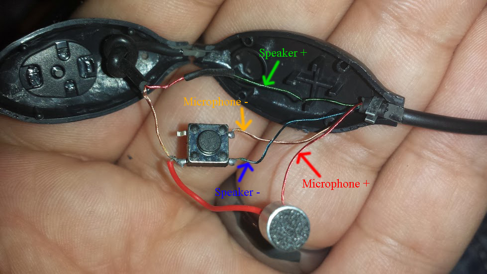
The green wire in the photo is the Speaker + connector, and that corresponds to the first mini pin (M1). The next wire of interest is the red wire, which is the Microphone + wire and corresponds to second contact on the big connector (B2). The gold wire shown is the Microphone – or Microphone ground wire, and that corresponds to the third big contact (B3). Finally, the blue wire is the speaker ground, speaker -, and it is the third mini contact (M3). If your cable colors do not match, or they appear to be connected differently, it would be best for you to run a Continuity Test to verify.
Now that we have identified all the wires and their corresponding connector locations, it is time to build our cable following the schematic! I will leave the construction aspect up to you, as I can’t assume that everyone has a soldering iron. I would recommend that you purchase a solder iron and solder all the connections together and perhaps use heat shrink tubing to keep things nice and neat. However, you can simply twist the wires together and tightly wrap them in electrical tape or some other kind of tape. Just make sure to make it a nice and secure connection that won’t fall apart. There’s nothing more difficult than having to tear apart tons of electrical tape to try and find a loose wire. So perhaps when you go get those 4 resistors you can take a look at what they have for soldering irons. Even the cheapest iron would be more than adequate for soldering a few wires. If you hang around this blog for a while, chances are you will put it to use again for another simple yet highly useful project in the future!
At the beginning of the article, I mentioned that you can choose to skip the resistors, and that I would give you some tips on working with a direct cable to cable connection. As mentioned, the voltage coming from the speakers is too high and can eventually damage the connectors if used this way long term. In addition, if it is too high, there will be the tendency for the signal to saturate the inputs and get clipped, so much so that the encoded packet data in the signal may be lost. The best thing you can do without the resistors in place is to make sure that you set your smartphone volume to the lowest sound level, and set your radio volume to the lowest sound setting as well. This should reduce the voltage levels and hopefully put you in an output level that won’t saturate the inputs. I will admit, that my very first test of this concept I used a direct connection without the resistors. What I found was that I could receive APRS packets fairly well with the volume set to minimum, but my transmissions were only about 10% effective.
In Part IV, I talk about setting up the software on your Smartphone and getting setup to use your hardware!