
Safety is important to us, and we chose to use a SPOT CONNECT Satellite Messenger as a fail safe device in case things go wrong in the field and we need urgent help. The SPOT device was designed to be versatile, portable, and rugged. A part of achieving portability is to function using batteries — very specialized Energizer Ultimate Lithium batteries that are expensive and difficult to find in more remote cities. Our SPOT device sits inside of our vehicle 99% of the time, and yet we were still consuming a pair of these batteries every 4 days when using the active tracking features. We were surprised and a bit disappointed that SPOT did not offer a 12V vehicle power option, since the performance of the device would be more reliable having a consistent power source. After further researching the device, we decided to develop a solution that would retain all portability and ruggedness of the SPOT device while allowing us to plug it in to the vehicles power.
The first step in the development process involved figuring out just why SPOT insists that the device be used with the Energizer Ultimate Lithium batteries exclusively. We wondered if it was a result of needing a specific steady voltage over the battery life cycle, or if the current demands from the SPOT device were too much for a standard lithium battery. So we opened up the device to take a look at its insides and do some testing. You start by taking the back cover off your SPOT device and removing the batteries. The first thing you notice when you start the tear down is another warning on the circuit board that reads: “AA Lithium Batteries Only.”

We started by removing the four screws that hold the top cover to the bottom body. The SOS switch cover must also be slid off before the two parts can be separated. Once the screws and button cover are off, you can gently pry at the side seam and separate the two pieces. It will take some, but not much effort to do this, since the device creates a seal to keep water out. When you separate the two pieces, you are presented with this:
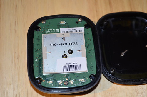
You can see the top piece is the antenna. Notice the tuning etching performed at the factory. This is why they tell you it is important to keep the SPOT device oriented so that the top faces the sky. There are 3 screws holding the circuit board to the device base. Remove the three screws and you can separate the whole assembly from its casing as shown in the next image.
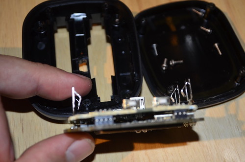
Its clear that the SPOT device was engineered to maximize the usage of space within its casing. Part of our objective in opening the device was to see if it would be feasible to internally mount provisions for an external power source. There is certainly no viable location available. The SPOT Connect is designed as a 2 piece assembly, and you can see in the above image how the two circuit board are mated via a header pin array. Here is a closer look at the circuit board from the battery contact side.
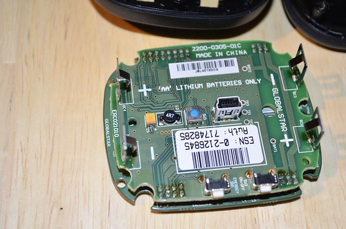
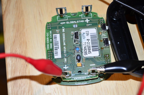
You can see pretty clearly in this image that 2 of the contacts (BC2 and BC4) are connected via a trace on the circuit board. The negative contact to Battery #1 at BC2 is connected to the positive contact of Battery #2 at BC4. This means that the 2 Lithium batteries are connected in series, and are therefore setup to provide the device with a 3.0V supply (1.5V + 1.5V). This can be further verified by running a continuity test at BC2 and BC4 as shown below.
So now we know that BC1 and BC3 are the + and – inputs for a 3V supply source. I connected a power supply to those leads and set it to 3.0V and the SPOT device came on. I noticed that at idle, the current was only about 20mA. That number went up when a Bluetooth connection was made, and it peaked at about 600mA when it initiated a message transmission while indoors. This was an intermittent rise in current, and once the message was transmitted, it went back down. Maximum power draw occurred at this state, when transmitting a message with a bad signal while maintaining an active Bluetooth connection.
So back to the original question set, is the voltage very sensitive? To answer the question, I set the voltage to 2.8V on the power supply. The device continued to function, and not only function, but it also did not light up the Low Battery indicator LED. 3.2V and 3.5V were also acceptable levels, causing no adverse effects (as expected). Prior to testing out higher voltages, I measured a brand new set of Energizer Lithium Ultimate batteries. What I found was that the batteries were anywhere from 1.78V to 1.85V for my batch, right out of the packaging. A near dead one measured 1.52V then when it got down to almost nothing, went down to about 1.35V, but this happened at over 95% depletion. A traditional Alkaline battery will start at these higher levels, but will drop down into the 1.5, 1.4, 1.3V range a lot earlier, at about 50% life, its at 1.5V already, and dies out at about 1.1-1.2V. They also suffer a lot when a higher current demand is placed on them and they are not at > 50% charge, resulting in fluctuating voltages.
After reading the specs for the Energizer Ultimate Lithium batteries and traditional Alkaline batteries, it is clear that they require the Lithium batteries because they maintain a voltage level above 1.5V for almost their entire useable life. They also tend to be higher capacity, and hence SPOT can guarantee a specific amount of operating time for the device. Given my research, I went ahead and made my own solution. It is simple, and cost about $10 to make.
I used an LM317 adjustable voltage regulator. This regulator will regulate a supply up to 30V down to whatever voltage you want (you select it via a resistor network). If you look at the datasheet for an LM317, you will see how simple it is to setup. In fact, here is a link to a calculator that shows the circuit, and lets you put in resistor values and calculates the output for you. http://www.electronics-lab.com/articles/LM317/
Now, they show 2 capacitors in that diagram, and they are to filter some noise, but in this application, they are not necessary, and the input is just not that sensitive. I measured no fluctuation on the LM317DT that I used even when I put in 28V at the input, and even when the SPOT was in transmit mode sending a Check-in/OK message. So, the capacitors are definitely not needed.
For fitment, what I did was make a custom circuit board that fit into the “H” cavity where the batteries go, and sits on top of the center space where the USB connector is. Its perfect, because the “H” is not the same on both sides, so it also serves to help you “key” how to insert the adapter. The two spring connectors that are above the Power/Satellite/Message/SOS LEDs are the positive and negative inputs that we verified using a DMM. Make sure you plug in to the correct ones, and not the ones that are tied together, or you will simply short your supply when you power it on. Using the H, it is impossible to insert the board in the wrong direction, though, so you only have to get it right once. I measured the dimensions with a caliper, so if anyone wants to etch their own board and wants the measurements, just let me know.
The shopping list:
- 1 x Proto Board (either a perf board, or etch your own board)
- 1 x LM317DT (i used the DT, a TO-220 3 pin package)
- 1 x 220 ohm 1% resistor (you don’t need 1%, you can use a 5%, but, 1% is definitely better) [I used this for R1]
- 1 x 300 ohm 1% resistor (again, 1% good, 5% acceptable, just cherry pick em) [used this for R2] {So, with 220/330 resistors, that calculates to 2.95V, but in my case with 1% tolerance, I ended up with 3.02V. If you use 5%, I recommend 240/360}
- 2 x springy contacts (you can use a thicker bus wire, or thick wire as a contact also, basically anything that will make a positive connection with the spring contacts that are on the device and be rigid enough to maintain a connection).
- 1 x cigarette lighter plug
- 1 x red and black wire for +/- of whatever length you need.
- 1 x diode (optional, for reverse polarity protection, in case somehow you really manage to get the board in there incorrectly, or something else crazy happens through acts of God and Nature) [Put this on the cigarette plug side, to save space].
So, you will notice that a TO-220 package LM317 fits ride inside the cavity where 1 battery goes, plenty of space left. The 2 resistors of course can go on the other side, but really, can squeeze them all on one side if necessary.
Here is a photo of what that looks like:
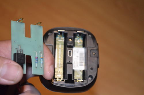
You can see the spring contacts I mentioned that I used there, too.
This is what it looks like when inserted into the device:
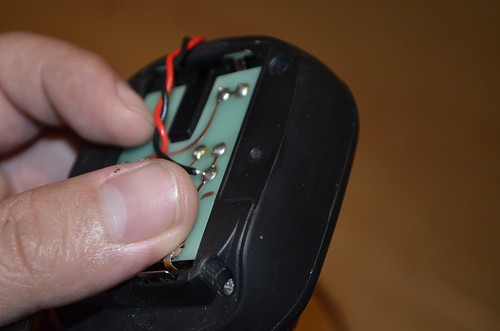
The springy contacts make contact with the +/- spring contacts on the device, and you’re good. The red and black wire have a cigarette lighter plug on it (I since added a sleeve for these). And you can cut a small notch in your battery cover to let them come out the side. I recommend ordering a new battery cover too, in case you want to use it with batteries and ensure that it can still float and stay dry per spec. But, if you can’t get a new cover, then you can still use the screw hole for the cover and go get a thin piece of plastic as a backing and screw it on to that hole so that it covers the back and holds the board in place, even if it doesn’t seal up like the standard lid.
That’s pretty much it. Now you can be sure that all your messages will go through, regardless of how long you are out, since it will get 100% power all the time.